Welcome to the Vanderbilt University STORM Lab MCR Developer’s Guide!
The goal of the STORM Lab’s Medical Capsule Robot (MCR) project is to systematize the development of miniaturized wireless devices by creating a cyber-physical design environment that will eliminate barriers in the design process, thus accelerating the progress to prototyping.
This guide is for developers who wish to use Vanderbilt’s modular architecture for their own project.
What you’ll need
- A Development Board
- An MCU module
- A wireless module
- Sensor and actuator modules as needed
- A Flexible Circuit
- An environment to write pure TinyOS applications, or Vanderbilt’s WebGME environment
Step 1: Getting started
Although the initial development for this project was focused around medical devices, the platform can be utilized for any project that necessitates rapid prototyping of a small, lightweight wireless system of sensors and actuators.
Connectivity between the sensor and actuator modules is achieved with a Flexible Circuit on which the modules are mounted before being folded to form the body of the MCR.
The backbone can host up to five different modules using 30-pin miniature connectors. The developer must keep in mind that the center slot is reserved for the MCU Module, and one slot is reserved for the Power Module. This leaves three modules available for sensors and actuators.
Step 2: Choose modules
There are currently 9 existing sensing modules and 1 existing actuation module for the MCR:

If your project requires a sensor or actuator that has not currently been developed for this platform, please refer to the Module Design Guide for important information.
Step 3: Write code
Just as the component-based approach on the hardware side is beneficial, we have developed a design environment utilizing TinyOS, which is a component-based operating system for wireless sensor networks and embedded devices. To program the MCU, you can either create your own application with TinyOS, or utilize the graphical design environment currently in development.
To get started writing a TinyOS application, follow the TinyOS Installation Guide for Ubuntu.
Step 4: Test and debug code
To test, debug, and eventually implement the code, there exists a Development Board with all of the functionalities of the flexible circuit, including an identical MCU and the same wireless capabilities. Refer to the Development Board Guide for more information on the board layout and functions.
We have developed a TinyOS platform called VUMCR that will serve as the make target for the application. For support with using the Development Board to port TinyOS, see the VUMCR Platform Support
Step 5: Install application on the flexible circuit
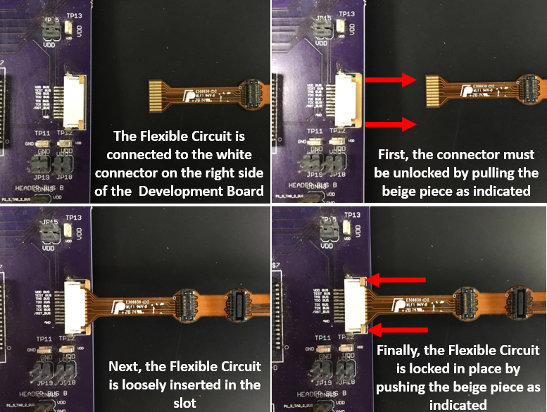
When the modules have all been tested and debugged on the Development Board, they must be attached to the 30-pin miniature connectors on the flex band. There is a small black circle on each module that must be aligned with the small white circle located on each slot of the Flexible Circuit. REMEMBER, slot A is designated for the Power Module, slot C is designated for the MCU, and the Wireless Module is docked on top of the MCU. The band must then be plugged into the Development Board and the application must be installed to the MCU on the flexible circuit. The following shows the proper way to attach the flexible circuit to the Development board:
Once the application has been installed, the band can be folded to fit into a smaller space. To most efficiently compress the band, follow the folding guide. NOTE: the largest gap between modules is between slots B and C, and the smallest gap is between C and D. This should help you with the initial orientation of the band.
