Development Board Guide
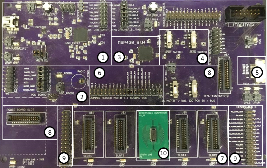
- EZ-FET
- Radio Communication
- MSP430 MCU
- Switches SW3, SW4
- Flexible Circuit Bus
- Jumper Header Between MSP and Global Bus
- Global Bus
- Power Board
- Debugging Pins
- Receptacle Adaptor
When the Development Board is first used, the EZ-FET (1) must be properly configured to program the board.
There are three different ways to download an application to an MSP430 MCU:
- Using the MCU on the board (3)
- Using an MCU module attached to the flexible circuit and connected to the board via the Flexible Circuit Bus (5)
- Using an MCU module nconnected to slot 3 of the Global Bus (7) using a Receptacle Adaptor (10)
Only one of the MCUs can be programmed at a time, so to avoid communication errors, only one MCU should be connected at a time. To differentiate which MCU to use, the switches in (4), and the headers in (6) must be correctly configured. To use the board’s MCU (3), the SW3 switch (4) must be switched to MSP mode. Jumpers must be connected across the pins in (6) to connect the board’s MCU (3) to the sensors and actuators from the Global Bus. It is important to remember that when using the board’s MCU, there mustn’t be an MCU module in slot C of the Global Bus, as this will cause communication errors. It is also important to note that The MCU on the board (3) can’t access the sensors or actuators when they are on the flexible band. If a modular MCU is the desired target, the SW3 switch must be switched to BUS mode, and an MCU module must be connected via the flexible band in (5) OR in the Global Bus (7). The current layout of the Development Board has all of the slots of the Global Bus (7) electrically identical, meaning Pin 1 on slot A is electrically connected to Pin 1 on slots B, C, D, and E. This means that only one sensor can be tested at a time. Future versions will allow for more functionality of the Global Bus. These slots are also electrically connected to the debugging pins on either side of the Global Bus. This provides easy access to the signals for debugging purposes.